
N1MM Logger+ Configuration
- Download and Install N1MM Logger+
- Set up N1MM Logger+ Configuration
- Set up Digital Interface Window for MMTTY
- Set up 2Tone in a Receive-Only Window
- Set up Gritty in a Receive-Only Window
- Set up RTTY messages page 1 > F1 through F12
Detailed information on the Configuration Setup (called the Configurer) can be found on the N1MM Logger+ website here. Refer to N1MMplus.pdf. If you have not done so already, download N1MMplus.pdf from the N1MM website into the SupportFiles folder under the N1MM Logger+ folder as shown below. This way you always know where it is.
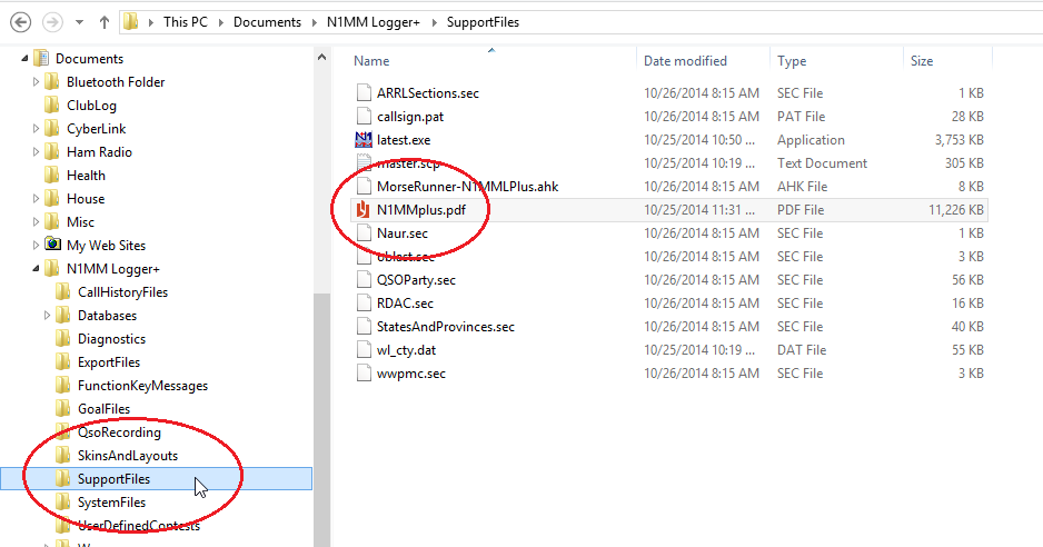
Figure 2-1
In the following steps, we are going to set up the configuration for N1MM Logger. This will include starting Radio Control (if your radio is connected to your computer), selecting Soundcard as your TU Type for use with MMTTY, and setting the path to MMTTY. Please note that when using MMTTY with N1MM Logger, COM port settings for PTT (and FSK, if used) are set up separately in MMTTY Setup. This is also true for selecting which soundcard you will use (if you have multiple sound cards in your PC). It is critical that MMTTY is working fully as a stand-alone program before attempting to use it with N1MM Logger+. If MMTTY is not working by itself as a stand-alone program, it will NOT work with N1MM Logger+.
1. Run N1MM Logger+ by double-clicking the icon on your desktop.
Figure 2-2
2. When you first start N1MM Logger+, the Entry Window may be on top of the Log Window. Drag the Entry Window away from the Log Window.
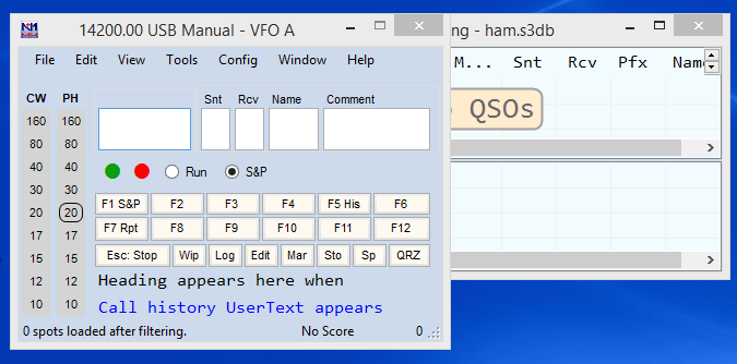
Figure 2-3 Entry Window on top of the Log Window
3. From the Entry Window, go to the Config menu and select Configure Ports, Mode Control, Audio, Other…
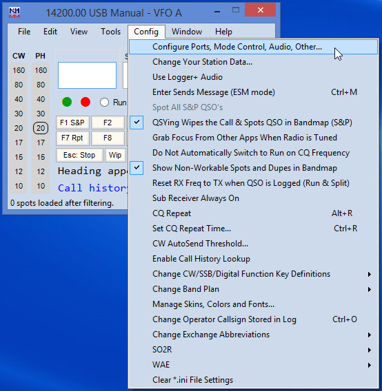
Figure 2-4
4. [wpanchor id=”step4″]The Configurer window will open to the Hardware tab screen. This is where you will configure your hardware – mainly radio. If your radio is connected to your computer and you have used Radio Control before with other programs, It is worthwhile to get Radio Control working first since you may already know how to do this. If you are not going to use Radio Control, then continue to Step 7.
To configure Radio Control, first close any program that may already be using radio control, such as DXLab Commander or any other logging program that uses Radio Control. In the Configurer window, select the port where your radio is connected in the Port pull-down menu (in the example below, COM 4 is used for radio control). Next select your radio in the Radio pull-down menu, then click on the Set button.
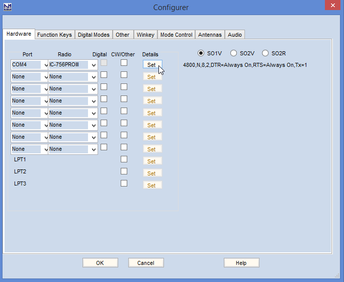
Figure 2-5
5.[wpanchor id=”step5″] In the next dialog screen you will set additional parameters for the COM port where the radio is connected. In this example, my Icom IC-756 PRO III is connected to COM port 4 and these are the settings. One very important part of this screen are the PTT options for Digital, SSB and CW modes. If you are going to use radio control to key PTT, then you must check the PTT via Radio Command Digital Mode check box. If you key PTT via a hardware device such as a homebrew transistor or commercial interface, then leave this box un-checked. It’s absolutely important that you do not enable both hardware and software PTT control at the same time. You won’t blow anything up but strange things could happen. If you are unsure which one to use, leave this un-checked. When you go to test your setup, if your radio doesn’t key then you can come back and check this box. I use a homebrew transistor (hardware) to key PTT, so I leave this box un-checked. When finished making changes, click OK.
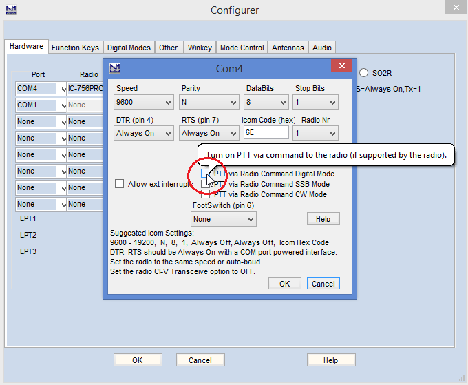
Figure 2-6
6. When you return to the Entry Window, the frequency of the radio may or may not show in the title bar. If your radio is in RTTY mode, it’s possible the frequency will not show. Instead, it may show Contact Mode (RTTY) <> Contest mode (MIXED)! There are a couple of ways to test radio control. One is to simply change the mode on the radio to CW. In CW mode, the frequency of the radio should show in the title bar of the Entry Window. and the band will be circled under the CW column.
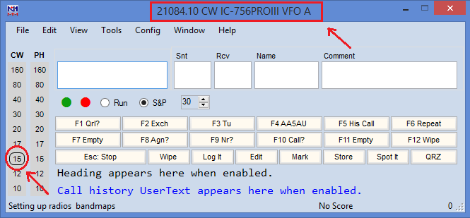
Figure 2-7
Another way to test radio control is to type a frequency, such as 14085, into the first open field of the Entry Window and hit Enter on your keyboard. If the radio goes to the frequency you typed, then radio control is working.
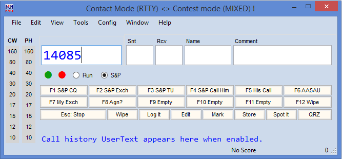
Figure 2-8
Yet another way to test radio control is to bring up the Bandmap from the Window menu.
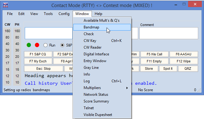
Figure 2-9
If the bandmap displays the frequency showing on the radio, then radio control is working. If radio control is not working, go back and revisit the parameters you entered in Steps 4 & 5.
7. [wpanchor id=”step7″]To set up to use MMTTY, click on the Digital Modes tab of Configurer. On the left hand side of the screen, Digital Interface 1 TU Type should be set to Soundcard. Under DI-1 MMTTY Setup, click MMTTY mode (AFSK or FSK) you will be using to transmit RTTY, then click on Select.
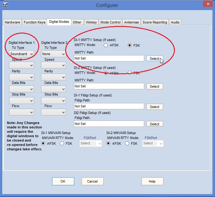
Figure 2-10
8. When the Open Files dialog screen opens, navigate to the location of MMTTY.EXE. Click on MMTTY.EXE, then click Open.
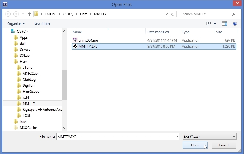
Figure 2-11
9. Confirm the Digital Interface 1 TU Type is set for Soundcard, the MMTTY Mode is set to either AFSK or FSK and the MMTTY Path is set to the location of MMTTY.EXE. Now click OK.
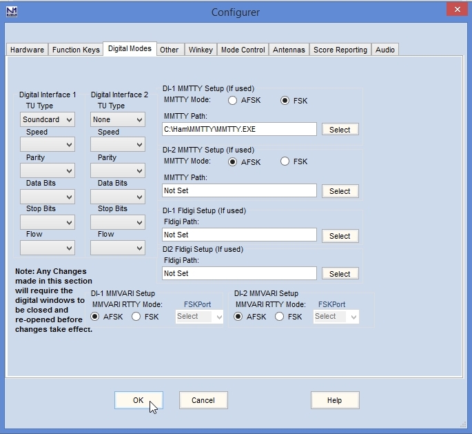
Figure 2-12
You are now ready to configure the Digital Interface for MMTTY.